The wheel is a circular mechanical assembly that, by means of rotation about an axis, makes it possible to replace sliding motion with rolling motion.
The wheel consists of the following components:
tread, covering, centre, bore and rolling actions.
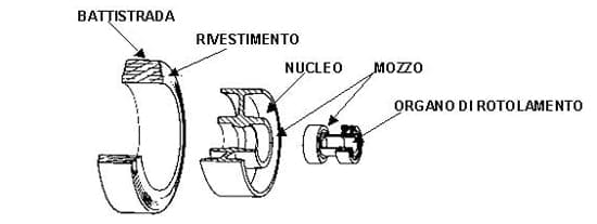
TREAD
The tread is the wheel’s outer surface, i.e. the part in contact with the ground. It can be smooth or sculpted with raised patterns to increase its grip on the ground.
COVERING
The covering, or rolling strip, is the outer ring, made of different materials and it characterises the wheel.
The covering is fixed when immovably fixed to the wheel centre (with adhesive or mechanical connection) or fitted when mechanically assembled on the centre.
CENTRE
The centre is the load-bearing component of the wheel that connects the covering to the bore.
The centre is made in various shapes and materials; it can be composed of a single piece or two or more parts joined together.
BORE AND ROLLING ACTIONS
The bore is the central part of the wheel that houses the axle or the rolling actions designed to facilitate rotation (ball bearings, roller bearings, plain bearings, etc.).
Depending on the construction methods and covering materials, wheels can be divided into four families: rubber wheeels, polyurethane, monolithic (or hard tread) and pneumatic.
Rubber Wheels (can be in Standard rubber, Elastic vulcanised rubber, or Thermoplastic rubber)
The covering of rubber wheels is composed of an elastomer made of natural rubber and/or synthetic rubber.
The rubber used for industrial wheels can be vulcanised or injection moulded.
In the first case, the rubber is mixed with suitable mineral fillers and vulcanising agents and then subjected the vulcanisation process. Vulcanisation changes the molecular structure of the rubber significantly: the soft material at the start of the process is transformed into a non-fusible product that assumes, and retains through time, the shape of the mould in which the reaction occurs. The thus-formed tyre is mechanically assembled to the centre. Vulcanised rubber features enhanced elastic deform-ability properties within relatively broad ranges of applied tensile and compression loads.
In the second case, the rubber undergoes a chemical synthesis process; the material obtained is then injected into a mould in which the centre has already been inserted. The injected rubber maintains its fusibility properties also after moulding.
The physical-mechanical characteristics of vulcanised rubber vary according to the quality of the natural and/or synthetic rubber used, the type and quantity of mineral fillers added and the conditions under which the vulcanisation process is performed.
Normally, the elastic properties of injection moulded rubber are inferior than those of top quality vulcanised rubber, while they are comparable to those of medium and low-quality vulcanised rubber.
The main physical-mechanical parameters relating to the quality of rubber are listed below (for a definition of each parameter, refer to the technical standard appearing alongside the parameter in question):
The above parameters are interdependent, i.e. a change in one parameter normally results in a change in the other parameters (to varying degrees).
The hardness parameter is the most readily measurable: in general, increased hardness is accompanied by a reduction of elastic properties (resilience, elongation at break, compression set) and
a reduction in overall performance of the wheel.
Conversely, parameters such as tear strength and abrasion loss depend mainly on the composition of the vulcanised rubber and, to a lesser extent, on the hardness value.
Polyurethane Wheels (mould-on polyurethane or thermoplastic polyurethane)
The covering of polyurethane wheels is composed of an elastomer obtained exclusively from synthetic raw materials.
Polyurethanes are chemical compounds obtained by means of a polymerisation reaction triggered by mixing two components belonging to two different families of compounds (Di-Isocyanates and Polyalcohols), that have been heated to temperatures such as to keep them in the liquid state with relatively low viscosity; elastomeric polyurethanes do not generally contain added mineral fillers. The reactive mixture is cast or injected into heated moulds containing the metal or plastic centres; the temperature of the mould and the centre it contains are such as to guarantee completion of the internal polymerisation reaction of the polyurethane and chemical anchorage of the polyurethane to the adhesive, if present, on the surface of the centre.
The broad range of compatible chemical compounds makes it possible to obtain an infinite number of elastomer formulations; it frequently occurs that the physical-chemical properties of the compound are similar in different stoichiometric formulations (“recipes”), but performance in operation can vary, also significantly, in accordance with the product employed.
Normally, mould-on polyurethane is no longer fusible, has good elasticity characteristics in addition to medium-high hardness and compressive and tensile strength.
Injected polyurethane is fusible even after moulding, and it generally has lower elastic properties but greater hardness with respect to mould-on polyurethane.
The main physical-mechanical parameters of polyurethane are as follows (for a definition of each parameter refer to the technical standard appearing alongside the parameter in question):
Monolithic Wheels
In monolithic (hard tread) wheels, the centre and the covering are made of the same material. The wheel’s physical-mechanical characteristics vary in accordance with the material used.
Engineering cast iron and thermoplastics are among the materials most frequently used to make this type of wheel.
Pneumatic Wheels
A pneumatic wheel covering consists of a rubber tyre with fabric insert and inner tube, assembled on the centre. The tread can be sculpted or grooved to increase the grip of the wheel on the ground.
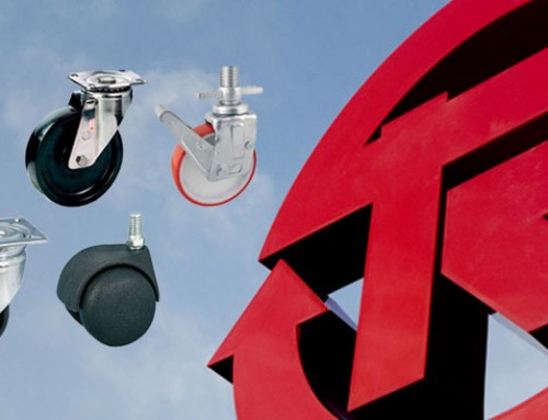
The castor is the connecting element between wheel and trolley*. Normally, all wheels required a castor in order to be assembled to the trolley; wheels whose axle forms part of the trolley form an exception to this rule.
Castors can be of the swivel or fixed type.
*”Trolley” is conventionally intended as any apparatus or machine to which wheels and castors are attached in order to facilitate handling.
Swivel Castor
The swivel castor rotates about its vertical axis to accommodate changes in the travel direction of the wheel. The wheel axis is offset with respect to the castor axis in order to achieve optimal manoeuvrability of the trolley.
“Manoeuvrability” is the ability of the trolley to change direction, while “directionality” refers to the ability of the trolley to maintain a specific trajectory.
An excessively large offset reduces trolley directionality due to oscillation of the wheel (swimmy effect).
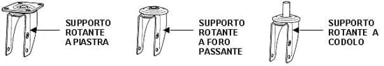
Depending on the type of attachment to the trolley, swivel castors can be constructed with an attachment plate, a through-hole or a stem.
Swivel castors with a stem can be equipped with different stem types and sizes, the main options being: threaded stem, plain stem, expansion stem, depending on how the assembly is attached to the trolley.
Swivel castors may also be equipped with brakes.
A brake is a device that makes it possible to prevent rotation of exclusively the wheel, exclusively the castor, or both wheel and castor simultaneously.
The components of a swivel castor are: attachment plate, fork, ball race ring, swivel actions, central pin and, potentially, dust seal.
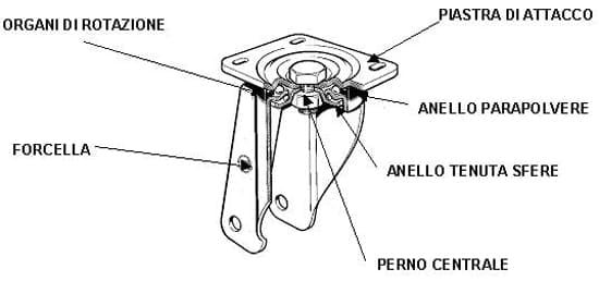
Attachment plate
The attachment plate is the element that connects the castor to the trolley. The attachment plate can be of various shapes:
– Rectangular with four attachment holes;
– Square with four attachment holes;
– Triangular with three attachment holes;
– Circular with through hole;
– Circular with stem.
Fork
The fork is an element with a characteristic inverted “U” shape that holds the wheel. There are holes at the bottom of the fork to accept the wheel’s axle set, while the swivel actions are located at the top.
Ball race ring (ATS)
The ball race ring contains the castor’s swivel actions. In special cases, it may have exclusively dust seal or protective functions.
Swivel actions
The swivel actions allow the plate to rotate on the fork. They consist of rings of balls between the plate and the fork (‘ball races’) or ball bearings, taper roller bearings, or axial bearings, appropriately lubricated with grease to protect against dust, liquids and other aggressive agents.
The castor load capacity varies significantly according to the type of swivel actions.
Central pin
The central pin is the element that joins the plate and the ball race ring (ATS). The plate and ball race ring thus form a single piece, while the fork is free to rotate about its own axis.
The pin can be:
– integral with the plate, made by pressing following by riveting performed after assembly of the components;
– integral with the plate, made by hot forming on the plates and successive locking with a self-locking nut;
– composed of a commercial screw and nut.
Dust seal
The dust seal protects the rotating actions of the swivel castor. The seal protects the actions from dust and solid aggressive agents of medium particle size.
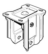
Fixed Castor
 The fixed castor is designed to keep the wheel on a straight trajectory and thus guarantees directionality of the trolley, while manoeuvrability of the trolley depends on the use of swivel castors.
The fixed castor is generally made of a single piece of pressed sheet steel in the shape of an inverted “U”. The two bottom ends of the “U” have holes to accommodate the wheel axle set, while the top has holes for fixing to the trolley.
The axle set is the connecting element that allows the wheel to be assembled to the castor. It normally consists of a threaded pin with nut, washers, tube and, where necessary, spacers.
For lightweight applications, the axle set can be formed with a rivet clenched directly on the castor fork.

Leave A Comment
You must be logged in to post a comment.